Air-Fuel Ratio

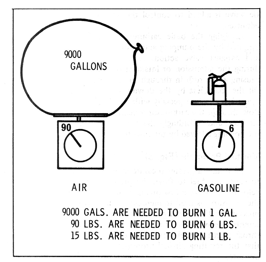
Fig. 3—Air-Fuel Weight Ratio
For those who may be wondering why we are speaking in terms of "pounds" of fuel instead of our more usual gallon measure, let's take a moment for clarification. Actually the reason we speak in terms of pounds rather than gallons is so that the ratio, or air-fuel mixture proportion, terms can be smaller numbers. For example, for most efficient (and economical) combustion, 9000 gallons of air are required to burn one gallon of gasoline, hence an air-fuel ratio of 9000:1 by volume. Obviously, proportions with such numerical differences would be difficult to comprehend and extremely awkward to work with for experimentation and design. By using weight as the base, let's make the same comparison (Fig. 3). A gallon of gasoline weighs about six pounds whereas 100 gallons of air are needed to produce one pound of air. Converting our volume air-fuel ratio to weight, we find that 9000 gallons of air weighs 90 pounds (100 gals. equals 1 lb., therefore 9000 divided by 100 = 90 lbs.) and one gallon of gasoline weighs 6 pounds. 90 divided by 6 equals 15 therefore we arrive at an air-fuel ratio of 15:1 by weight.

Metering
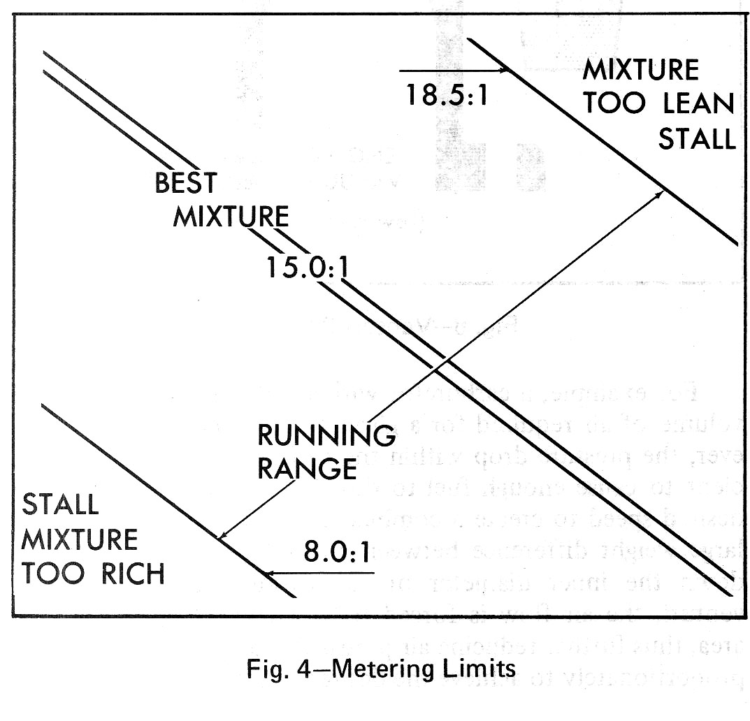
Good combustion demands a correct mixture ratio between fuel and air. To release all possible energy by combustion, the right amount of fuel must be mixed with a given amount of air. The metering job of the carburetor is to furnish the proper air-fuel ratio for all conditions, so that the engine operation will neither be too lean for power requirements nor too rich for economy (Fig. 4), while still meeting prime requirements of low emissions.

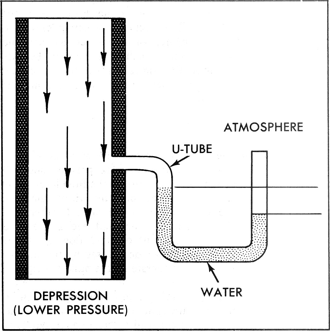
Air flow through a pipe will create a pressure drop within the pipe proportional to the speed of the air. Thus, for a given pipe size, the pressure difference between the outside air and the pressure within the pipe provides a direct means of measuring the amount of air flowing through the pipe. The simplest means of measuring the pressure difference between atmosphere and the pressure inside the pipe, is to insert a U-tube partially filled with water into the pipe as illustrated (Fig. 5). Since one end is open to atmosphere, the water level will rise on the low pressure (or pipe side) because water will flow toward an area of lower pressure. Actually, the water is being pushed into a state of balance by the weight of the air at the end of the U-tube open to atmosphere vacuum.

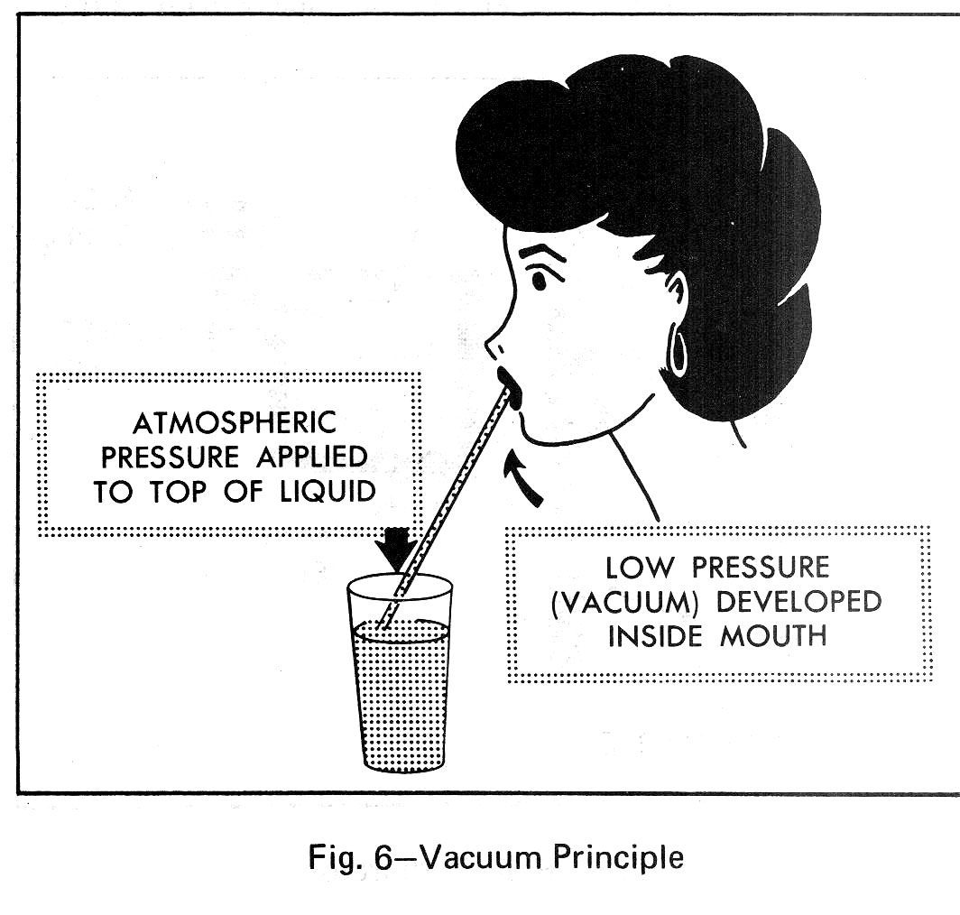
A common example of the force exerted by the weight of air is a drinking straw (Fig. 6). As you suck on a straw, the air within the straw is removed, thus creating a low pressure or vacuum. The weight, or pressure, of the air on the surface of the liquid in the glass then forces the liquid up the straw to fill the void. The important thing to understand is that fluid is not pulled by the vacuum but is rather pushed into the vacuum or low pressure area by the weight of the air pressing on the surface of the liquid.
The difference in pressure, or vacuum, is expressed by measuring the distance between the two heads of water in the U-tube, or inches of water. Low vacuum is generally expressed in inches of water but higher vacuum, such as manifold vacuum, is usually measured in inches of mercury because mercury is approximately 13 - 1/2 times heavier than water and thus provides a more convenient valve for measuring the larger pressure differences.
FUEL METERING
As shown in measurement of air flow with the U-tube, fluids flow when there is a difference in pressure and will always flow toward the lower pressure. If the fluid level in the U-tube were higher, the reduced pressure within the pipe would cause the fluid to flow into the pipe. Further, if a means were provided to maintain the fluid level at a desired height in the U-tube, the amount of fluid flow would be proportional to the pressure difference caused by the air flow through the pipe. Carburetors operate on the basic principle of pressure difference. A basic carburetor is an adaptation of the U-tube (Fig. 7). The fuel side, open to atmospheric pressure, inside of air cleaner (internal venting), is enlarged to create a reservoir and fitted with a float valve to maintain a constant level of fuel. To control the quantity of fuel delivered, a jet or metering orifice is screwed into the base of the main nozzle.
A streamlined restriction, known as a venturi, is added to the air intake side to create an additional pressure drop for a given rate of air flow, dictated by upper diameter of the pipe. Finally, a throttle valve is added to control the volume of air-fuel mixture admitted. Applying the basic carburetor to an engine, air flow is initiated by the pumping action of the pistons and the intake and exhaust valve action. As the piston moves downward during the admission or intake stroke, the inlet valve is open causing air to rush in through the carburetor and manifold to fill the space left by the downward piston travel. At engine operating speeds, especially with multi-cylinder engines, the air flow through the carburetor is nearly constant. The amount of air flow, and accordingly the fuel picked up, is controlled by the opening allowed by the throttle valve.
next: Venturi Principle
